STM32H747I Discovery
Overview
The discovery kit enables a wide diversity of applications taking benefit from audio, multi-sensor support, graphics, security, video, and high-speed connectivity features.
The board includes an STM32H747XI SoC with a high-performance DSP, Arm Cortex-M7 + Cortex-M4 MCU, with 2MBytes of Flash memory, 1MB RAM, 480 MHz CPU, Art Accelerator, L1 cache, external memory interface, large set of peripherals, SMPS, and MIPI-DSI.
Additionally, the board features:
On-board ST-LINK/V3E supporting USB reenumeration capability
USB ST-LINK functions: virtual COM port, mass storage, debug port
Flexible power-supply options:
ST-LINK USB VBUS, USB OTG HS connector, or external sources
4” capacitive touch LCD display module with MIPI® DSI interface
Ethernet compliant with IEEE802.3-2002
USB OTG HS
Stereo speaker outputs
ST-MEMS digital microphones
2 x 512-Mbit QUAD-SPI NOR Flash memory
256-Mbit SDRAM
4 color user LEDs
1 user and reset push-button
4-direction joystick with selection button
Arduino Uno V3 connectors
More information about the board can be found at the STM32H747I-DISCO website. More information about STM32H747XIH6 can be found here:
Supported Features
The stm32h747i_disco board supports the hardware features listed below.
- on-chip / on-board
- Feature integrated in the SoC / present on the board.
- 2 / 2
-
Number of instances that are enabled / disabled.
Click on the label to see the first instance of this feature in the board/SoC DTS files. -
vnd,foo -
Compatible string for the Devicetree binding matching the feature.
Click on the link to view the binding documentation.
stm32h747i_disco/stm32h747xx/m4 target
On-target memory for this board target: 128 KiB of RAM, 1 MiB of Flash.
Type |
Location |
Description |
Compatible |
|---|---|---|---|
CPU |
on-chip |
ARM Cortex-M4F CPU1 |
|
ADC |
on-chip |
STM32 ADC4 |
|
Audio |
on-chip |
STMicroelectronics DFSDM block1 |
|
on-chip |
STMicroelectronics DFSDM DMIC4 |
||
CAN |
on-chip |
STM32H7 series (and compatible) FDCAN CAN FD controller2 |
|
Clock control |
on-chip |
STM32H7 RCC (Reset and Clock controller)1 |
|
on-chip |
STM32 HSE Clock1 |
||
on-chip |
STM32 HSI Clock1 |
||
on-chip |
Generic fixed-rate clock provider3 |
||
on-chip |
STM32 LSE Clock1 |
||
on-chip |
STM32H7 main PLL3 |
||
on-chip |
STM32 Clock multiplexer1 |
||
on-chip |
STM32 Microcontroller Clock Output (MCO)2 |
||
Comparator |
on-chip |
STM32H7 series Comparator2 |
|
Counter |
on-chip |
STM32 counters14 |
|
CRC |
on-chip |
STM32 CRC calculation unit1 |
|
DAC |
on-chip |
STM32 family DAC1 |
|
Display |
on-chip |
STM32 LCD-TFT display controller1 |
|
DMA |
on-chip |
STM32 DMA controller (V1)2 |
|
on-chip |
STM32 BDMA controller1 |
||
on-chip |
STM32 DMAMUX controller2 |
||
Ethernet |
on-chip |
STM32H7 Ethernet1 |
|
on-chip |
STM32 MDIO Controller1 |
||
Flash controller |
on-chip |
STM32 Family flash controller1 |
|
GPIO & Headers |
on-chip |
STM32 GPIO Controller11 |
|
on-board |
GPIO pins exposed on Arduino Uno (R3) headers1 |
||
on-board |
GPIO pins exposed on a Digilent Pmod interface1 |
||
on-board |
GPIO pins exposed on QSH-030-01-F-D-A connector used as DSI LCD connector1 |
||
on-board |
GPIO pins exposed on the 30-pin ZIF connector (CN5) of the B-CAMS-OMV1 |
||
I2C |
on-chip |
STM32 I2C V2 controller4 |
|
I2S |
on-chip |
STM32H7 I2S controller3 |
|
on-chip |
STM32 SAI Block controller1 |
||
Input |
on-board |
Group of GPIO-bound input keys1 |
|
Interrupt controller |
on-chip |
ARMv7-M NVIC (Nested Vectored Interrupt Controller)1 |
|
on-chip |
STM32 External Interrupt Controller1 |
||
IPM |
on-chip |
STM32 HSEM MAILBOX1 |
|
LED |
on-board |
Group of GPIO-controlled LEDs1 |
|
Memory controller |
on-chip |
STM32 Battery Backed RAM1 |
|
on-chip |
STM32H7 Flexible Memory Controller (FMC)1 |
||
on-chip |
STM32 Flexible Memory Controller (SDRAM controller)1 |
||
MIPI-DSI |
on-chip |
STM32 MIPI DSI host1 |
|
MMC |
on-chip |
STM32 SDMMC Host Controller2 |
|
MTD |
on-chip |
STM32 flash memory1 |
|
NVMEM |
on-chip |
Fixed layout for Non-Volatile memory1 |
|
OTP memory |
on-chip |
STM32 embedded NVM OTP1 |
|
PHY |
on-chip |
This binding is to be used by all the usb transceivers which are built-in with USB IP1 |
|
Pin control |
on-chip |
STM32 Pin controller1 |
|
Power management |
on-chip |
STM32H7 power controller1 |
|
PWM |
on-chip |
STM32 PWM12 |
|
QSPI |
on-chip |
STM32 QSPI Controller1 |
|
Reset controller |
on-chip |
STM32 Reset and Clock Control (RCC) Controller1 |
|
RNG |
on-chip |
STM32 Random Number Generator1 |
|
RTC |
on-chip |
STM32 RTC1 |
|
Sensors |
on-chip |
STM32 quadrature decoder6 |
|
on-chip |
STM32 family TEMP node for production calibrated sensors with two calibration temperatures1 |
||
on-chip |
STM32 VBAT1 |
||
on-chip |
STM32 VREF+1 |
||
Serial controller |
on-chip |
STM32 USART4 |
|
on-chip |
|||
on-chip |
STM32 LPUART1 |
||
SMbus |
on-chip |
STM32 SMBus controller4 |
|
SPI |
on-chip |
STM32H7 SPI controller6 |
|
Timer |
on-chip |
ARMv7-M System Tick1 |
|
on-chip |
STM32 timers14 |
||
on-chip |
STM32 low-power timer (LPTIM)1 |
||
USB |
on-chip |
STM32 OTGHS controller1 |
|
on-chip |
STM32 OTGFS controller1 |
||
Video |
on-chip |
STM32 DCMI1 |
|
on-chip |
STM32 JPEG HW Codec1 |
||
Watchdog |
on-chip |
STM32 watchdog1 |
|
on-chip |
STM32 system window watchdog1 |
stm32h747i_disco/stm32h747xx/m7 target
On-target memory for this board target: 512 KiB of RAM, 1 MiB of Flash.
Type |
Location |
Description |
Compatible |
|---|---|---|---|
CPU |
on-chip |
ARM Cortex-M7 CPU1 |
|
ADC |
on-chip |
STM32 ADC4 |
|
Audio |
on-chip |
STMicroelectronics DFSDM block1 |
|
on-chip |
STMicroelectronics DFSDM DMIC4 |
||
CAN |
on-chip |
STM32H7 series (and compatible) FDCAN CAN FD controller2 |
|
Clock control |
on-chip |
STM32H7 RCC (Reset and Clock controller)1 |
|
on-chip |
STM32 HSE Clock1 |
||
on-chip |
STM32 HSI Clock1 |
||
on-chip |
|||
on-chip |
STM32 LSE Clock1 |
||
on-chip |
|||
on-chip |
STM32 Clock multiplexer1 |
||
on-chip |
STM32 Microcontroller Clock Output (MCO)2 |
||
Comparator |
on-chip |
STM32H7 series Comparator2 |
|
Counter |
on-chip |
STM32 counters14 |
|
CRC |
on-chip |
STM32 CRC calculation unit1 |
|
DAC |
on-chip |
STM32 family DAC1 |
|
Display |
on-chip |
STM32 LCD-TFT display controller1 |
|
DMA |
on-chip |
STM32 DMA controller (V1)2 |
|
on-chip |
STM32 BDMA controller1 |
||
on-chip |
STM32 DMAMUX controller2 |
||
Ethernet |
on-chip |
STM32H7 Ethernet1 |
|
on-chip |
STM32 MDIO Controller1 |
||
on-board |
Generic MII PHY1 |
||
Flash controller |
on-chip |
STM32 Family flash controller1 |
|
on-board |
STM32 QSPI Flash controller supporting the JEDEC CFI interface2 |
||
GPIO & Headers |
on-chip |
STM32 GPIO Controller11 |
|
on-board |
GPIO pins exposed on Arduino Uno (R3) headers1 |
||
on-board |
GPIO pins exposed on a Digilent Pmod interface1 |
||
on-board |
GPIO pins exposed on QSH-030-01-F-D-A connector used as DSI LCD connector1 |
||
on-board |
GPIO pins exposed on the 30-pin ZIF connector (CN5) of the B-CAMS-OMV1 |
||
I2C |
on-chip |
||
I2S |
on-chip |
STM32H7 I2S controller3 |
|
on-chip |
STM32 SAI Block controller1 |
||
Input |
on-board |
Group of GPIO-bound input keys1 |
|
Interrupt controller |
on-chip |
ARMv7-M NVIC (Nested Vectored Interrupt Controller)1 |
|
on-chip |
STM32 External Interrupt Controller1 |
||
IPM |
on-chip |
STM32 HSEM MAILBOX1 |
|
LED |
on-board |
Group of GPIO-controlled LEDs1 |
|
Memory controller |
on-chip |
STM32 Battery Backed RAM1 |
|
on-chip |
STM32H7 Flexible Memory Controller (FMC)1 |
||
on-chip |
STM32 Flexible Memory Controller (SDRAM controller)1 |
||
MIPI-DSI |
on-chip |
STM32 MIPI DSI host1 |
|
MMC |
on-chip |
||
MMU / MPU |
on-chip |
ARMv7-M Memory Protection Unit (MPU)1 |
|
MTD |
on-chip |
STM32 flash memory1 |
|
on-board |
Fixed partitions of a flash (or other non-volatile storage) memory1 |
||
NVMEM |
on-chip |
Fixed layout for Non-Volatile memory1 |
|
OTP memory |
on-chip |
STM32 embedded NVM OTP1 |
|
PHY |
on-chip |
This binding is to be used by all the usb transceivers which are built-in with USB IP1 |
|
on-board |
This binding is to be used by all the usb transceivers which are an external ULPI phy1 |
||
Pin control |
on-chip |
STM32 Pin controller1 |
|
Power management |
on-chip |
STM32H7 power controller1 |
|
PWM |
on-chip |
STM32 PWM12 |
|
QSPI |
on-chip |
STM32 QSPI Controller1 |
|
Reset controller |
on-chip |
STM32 Reset and Clock Control (RCC) Controller1 |
|
RNG |
on-chip |
STM32 Random Number Generator1 |
|
RTC |
on-chip |
STM32 RTC1 |
|
Sensors |
on-chip |
STM32 quadrature decoder6 |
|
on-chip |
STM32 family TEMP node for production calibrated sensors with two calibration temperatures1 |
||
on-chip |
STM32 VBAT1 |
||
on-chip |
STM32 VREF+1 |
||
Serial controller |
on-chip |
||
on-chip |
STM32 UART4 |
||
on-chip |
STM32 LPUART1 |
||
SMbus |
on-chip |
STM32 SMBus controller4 |
|
SPI |
on-chip |
||
Timer |
on-chip |
ARMv7-M System Tick1 |
|
on-chip |
STM32 timers14 |
||
on-chip |
STM32 low-power timer (LPTIM)1 |
||
USB |
on-chip |
STM32 OTGHS controller1 |
|
on-chip |
STM32 OTGFS controller1 |
||
Video |
on-chip |
STM32 DCMI1 |
|
on-chip |
STM32 JPEG HW Codec1 |
||
Watchdog |
on-chip |
STM32 watchdog1 |
|
on-chip |
STM32 system window watchdog1 |
Pin Mapping
STM32H747I Discovery kit has 9 GPIO controllers. These controllers are responsible for pin muxing, input/output, pull-up, etc.
For more details please refer to STM32H747I-DISCO website.
Default Zephyr Peripheral Mapping:
UART_1 TX/RX : PA9/PA10 (ST-Link Virtual Port Com)
UART_8 TX/RX : PJ8/PJ9 (Arduino Serial)
SPI_5 NSS/SCK/MISO/MOSI : PK1/PK0/PJ11/PJ10 (Arduino SPI)
SDMMC_1 D0/D1/D2/D3/CK/CMD: PC8/PC9/PC10/PC11/PC12/PD2
LD1 : PI12
LD2 : PI13
LD3 : PI14
LD4 : PI15
W-UP : PC13
J-CENTER : PK2
J-DOWN : PK3
J-LEFT : PK4
J-RIGHT : PK5
J-UP : PK6
System Clock
The STM32H747I System Clock can be driven by an internal or external oscillator, as well as by the main PLL clock. By default, the CPU1 (Cortex-M7) System clock is driven by the PLL clock at 400MHz, and the CPU2 (Cortex-M4) System clock is driven at 200MHz. PLL clock is feed by a 25MHz high speed external clock.
Serial Port
The STM32H747I Discovery kit has up to 8 UARTs. Default configuration assigns USART1 and UART8 to the CPU1. The Zephyr console output is assigned to UART1 which connected to the onboard ST-LINK/V3.0. Virtual COM port interface. Default communication settings are 115200 8N1.
Ethernet
Disclaimer: This section is mostly copy-paste of corresponding DISCO_H747I modifications for Ethernet mbed blog post. The author of this article sincerely allowed to use the images and his knowledge about necessary HW modifications to get Ethernet working with this board.
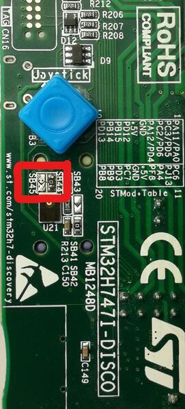
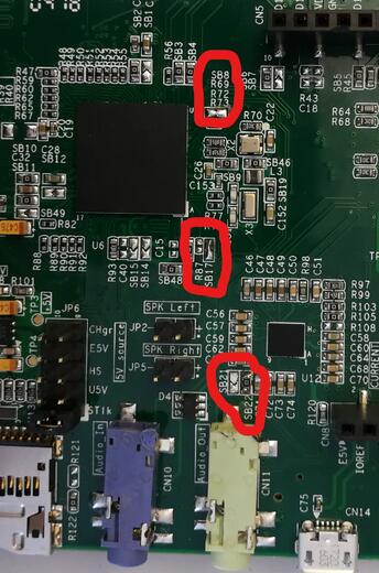
To get Ethernet working following HW modifications are required:
SB21, SB45 and R87 should be opened
SB22, SB44, SB17 and SB8 should be closed
Following two images shows necessary changes on the board marked:
Display
The STM32H747I Discovery kit has a dedicated DSI LCD connector CN15, where
the MB1166 (B-LCD40-DSI1) display extension board can be mounted. Enable display
support in Zephyr by adding the shield st_b_lcd40_dsi1_mb1166 or
st_b_lcd40_dsi1_mb1166_a09 to your build command, for example:
# From the root of the zephyr repository
west build -b stm32h747i_disco/stm32h747xx/m7 --shield st_b_lcd40_dsi1_mb1166 samples/drivers/display
west flash
Note
The shield comes in different hardware revisions, the MB1166-A09
is utilizing a NT35510 panel controller and shall specifically
use st_b_lcd40_dsi1_mb1166_a09 as SHIELD when building.
Prior versions are utilizing an OTM8009a controller and shall
use shield name without postfix, that is: st_b_lcd40_dsi1_mb1166.
Shield version is printed on a sticker placed below the two bottom
mounting holes and has the format: MB1166-Axx.
Resources sharing
The dual core nature of STM32H747 SoC requires sharing HW resources between the two cores. This is done in 3 ways:
Compilation: Clock configuration is only accessible to M7 core. M4 core only has access to bus clock activation and deactivation.
Static pre-compilation assignment: Peripherals such as a UART are assigned in devicetree before compilation. The user must ensure peripherals are not assigned to both cores at the same time.
Run time protection: Interrupt-controller and GPIO configurations could be accessed by both cores at run time. Accesses are protected by a hardware semaphore to avoid potential concurrent access issues.
Programming and Debugging
The stm32h747i_disco board supports the runners and associated west commands listed below.
| flash | debug | attach | rtt | debugserver | reset | |
|---|---|---|---|---|---|---|
| jlink | ✅ | ✅ | ✅ | ✅ | ✅ | ✅ |
| openocd | ✅ | ✅ (default) | ✅ | ✅ | ✅ | |
| stm32cubeprogrammer | ✅ (default) |
STM32H747I-DISCO board includes an ST-LINK/V3 embedded debug tool interface.
Applications for the stm32h747i_disco board should be built per core target,
using either stm32h747i_disco/stm32h747xx/m7 or stm32h747i_disco/stm32h747xx/m4
as the target.
See Building an Application for more information about application builds.
Note
Check if the board’s ST-LINK V3 has the newest FW version. It can be updated using STM32CubeProgrammer.
Note
With OpenOCD, sometimes, flashing does not work. It is necessary to erase the flash (with STM32CubeProgrammer for example) to make it work again. Debugging with OpenOCD is currently working for this board only with Cortex M7, not Cortex M4.
Flashing
Flashing operation will depend on the target to be flashed and the SoC option bytes configuration.
The board is configured to be flashed using west STM32CubeProgrammer runner for both cores, so its installation is required. The target core is detected automatically.
Alternatively, OpenOCD or JLink can also be used to flash the board using
the --runner (or -r) option:
$ west flash --runner openocd
$ west flash --runner jlink
It is advised to use STM32CubeProgrammer to check and update option bytes configuration.
By default:
CPU1 (Cortex-M7) boot address is set to 0x80000000 (OB: BOOT_CM7_ADD0)
CPU2 (Cortex-M4) boot address is set to 0x81000000 (OB: BOOT_CM4_ADD0)
Also, default out of the box board configuration enables CM7 and CM4 boot when board is powered (Option bytes BCM7 and BCM4 are checked). It is possible to change Option Bytes so that CM7 boots first in stand alone, and CM7 will wakeup CM4 after clock initialization. Drivers are able to take into account both Option Bytes configurations automatically.
Zephyr flash configuration has been set to meet these default settings.
Flashing an application to STM32H747I M7 Core
First, connect the STM32H747I Discovery kit to your host computer using the USB port to prepare it for flashing. Then build and flash your application.
Here is an example for the Hello World application.
# From the root of the zephyr repository
west build -b stm32h747i_disco/stm32h747xx/m7 samples/hello_world
west flash
Run a serial host program to connect with your board:
$ minicom -D /dev/ttyACM0
You should see the following message on the console:
Hello World! stm32h747i_disco
Note
Sometimes, flashing is not working. It is necessary to erase the flash (with STM32CubeProgrammer for example) to make it work again.
Similarly, you can build and flash samples on the M4 target. For this, please take care of the resource sharing (UART port used for console for instance).
Here is an example for the Blinky application on M4 core.
# From the root of the zephyr repository
west build -b stm32h747i_disco/stm32h747xx/m4 samples/basic/blinky
west flash
Debugging
You can debug an application on Cortex M7 side in the usual way. Here is an example for the Hello World application.
# From the root of the zephyr repository
west build -b stm32h747i_disco/stm32h747xx/m7 samples/hello_world
west debug
Debugging a Zephyr application on Cortex M4 side with west is currently not available. As a workaround, you can use STM32CubeIDE.