Seeed Studio COB LED Driver Board for XIAO
Overview
The Seeed Studio COB LED Driver Board for XIAO [1] is a seven-channel lighting carrier for the Seeed Studio XIAO family. It exposes two high-power switched outputs on D0 and D1 plus four active-low PWM outputs on D2, D3, D8, and D9 for dimming effects.
In Zephyr, the shield provides two always-available GPIO-switched outputs on D0 and D1 and four
optional PWM outputs on D2, D3, D8, and D9. The base shield overlay always exposes the D0 and D1
outputs as led0 and led1. The PWM outputs are described by the shield, but they remain
disabled until a board-specific or application overlay routes them to PWM hardware on the attached
XIAO board.
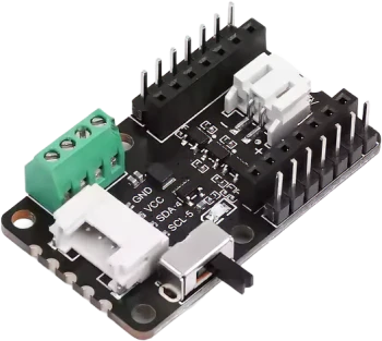
Seeed Studio COB LED Driver Board for XIAO (Credit: Seeed Studio)
Pin Assignments
XIAO pin |
Zephyr alias |
Function |
|---|---|---|
D0 |
|
High-power switched output 0 |
D1 |
|
High-power switched output 1 |
D2 |
|
Low-power PWM output 0, active low |
D3 |
|
Low-power PWM output 1, active low |
D8 |
|
Low-power PWM output 2, active low |
D9 |
|
Low-power PWM output 3, active low |
SDA / SCL |
N/A |
Grove I2C connector |
Requirements
This shield can be used with boards that expose the XIAO connector label (xiao_d).
The shield definition always provides GPIO LED aliases for the two high-power outputs on D0 and D1.
The four low-power outputs on D2, D3, D8, and D9 require PWM routing that depends on the attached
XIAO board. The shield defines pwm-led0 through pwm-led3 aliases for those outputs, but the
corresponding nodes stay disabled until a board-specific or application overlay provides PWM
controller, channel, and pinctrl configuration. The following section describes how this
configuration can be done.
PWM Configuration
Enabling PWM on specific pins requires PWM peripheral configuration that is specific to the board. Therefore, an overlay similar to boards/shields/seeed_xiao_cob_led/boards/xiao_esp32c6_esp32c6_hpcore.overlay must be supplied for your XIAO board (either alongside this shield as a board overlay or from your application). It should:
enable a PWM controller with 4 channels and the appropriate pin control configuration to assign them to the pins D2, D3, D8, and D9 of the shield,
add
pwmsproperties to the shield’spwm-led0throughpwm-led3nodes.
The low-power outputs on this shield use active-low logic, so set PWM_POLARITY_INVERTED on each
pwms entry.
Programming
Set --shield seeed_xiao_cob_led when invoking west build.
For example, to use the high-power D0 output with Blinky:
# From the root of the zephyr repository
west build -b xiao_esp32c6/esp32c6/hpcore --shield seeed_xiao_cob_led samples/basic/blinky
As a reminder, to use the PWM outputs, you need to provide PWM routing configuration in a Devicetree
overlay. The included xiao_esp32c6/esp32c6/hpcore shield overlay allows to build the
PWM Blinky sample as follows:
# From the root of the zephyr repository
west build -b xiao_esp32c6/esp32c6/hpcore --shield seeed_xiao_cob_led samples/basic/blinky_pwm