X-NUCLEO-IKS5A1: MEMS Inertial and Environmental Multi sensor shield
Overview
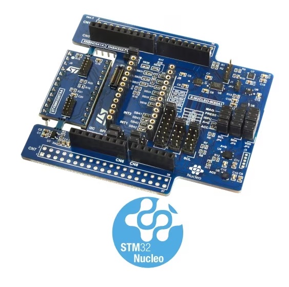
The X-NUCLEO-IKS5A1 is an industrial motion MEMS and environmental sensor evaluation board kit composed by:
X-NUCLEO-IND5A1: the main board, it hosts the motion MEMS and environmental sensors.
STEVAL-MKGI07A: a detachable add-on board, which hosts two industrial connectors.
The X-NUCLEO-IKS5A1 expansion board allows application development with features like FSM, MLC, ISPU, and sensor hub (with ISM330IS and ISM6HG256X onboard).
More general information about the board can be found at the X-NUCLEO-IKS5A1 website.
Hardware Description
X-NUCLEO-IKS5A1 provides the following key features:
Wide range of industrial motion and environmental sensors:
ISM6HG256X: intelligent IMU with simultaneous low-g and high-g acceleration detection
ISM330IS: 6-axis IMU, always-on 3-axis accelerometer and 3-axis gyroscope with ISPU
IIS2DULPX: intelligent ultralow power accelerometer for industrial applications
ILPS22QS: dual full-scale, 1260 hPa and 4060 hPa, absolute digital output barometer
IIS2MDC: high accuracy, ultralow power, 3-axis digital output magnetometer
DIL24 socket and industrial connectors for external sensors
Compatible with X-CUBE-MEMS1, an expansion software package for STM32Cube
I2C sensor hub features on ISM330IS and ISM6HG256X available
Supported by MEMS-Studio, a software solution for MEMS sensors with graphical no-code design of algorithms and development of embedded AI features
Compatible with STM32 Nucleo boards
Equipped with Arduino UNO R3 connector
RoHS compliant and WEEE compliant
Hardware Configuration
X-NUCLEO-IKS5A1 board can be configured in five different modes, which can be selected through J4 and J5 jumpers. Additional information about X-NUCLEO-IKS5A1 configuration modes and how sensors are connected together can be found in the X-NUCLEO-IKS5A1 user manual
Mode 1: Standard Mode
In standard I2C mode, all devices are connected to an external main board via the same I2C bus.
The board configuration is:
J4: 1-2, 9-10 (HUB2_SCx = GND, STM_SCL = SENS_SCL)
J5: 1-2, 9-10 (HUB2_SDx = GND, STM_SDA = SENS_SDA)
JP6, JP8, JP9, JP10 closed in I2C
Mode 2: ISM330IS SensorHub Mode (SHUB2)
In this sensor hub I2C mode, it is possible to power up the 6-axes inertial measurement unit (IMU) functionalities by collecting external data through a direct control of the on-board environmental sensors (magnetometer, sensor) and external sensor (DIL24) through the auxiliary I2C bus “SENS_I2C”. ISM6HG256X and IIS2DULPX remain connected to the main bus “uC_I2C” coming from the external boards.
The board configuration is:
J4: 3-4 (HUB1_SCx = SENS_SCL)
J5: 3-4 (HUB1_SDx = SENS_SDA)
Mode 3: ISM6HG256X I2C sensor hub
In this sensor hub I2C mode, it is possible to power up the 6-axes IMU functionalities by collecting external data through a direct control of the on-board environmental sensors (magnetometer, sensor) and external sensor (DIL24) through the auxiliary I2C bus “SENS_I2C”. ISM330IS and IIS2DULPX remain connected to the main bus “uC_I2C” coming from the external boards.
The board configuration is:
J4: 5-6 (HUB_SCx = SENS_SCL)
J5: 5-6 (HUB_SDx = SENS_SDA)
Mode 4: DIL24 SensorHub Mode
In this case, a sensor with embedded sensor hub functionality is mounted to the X-NUCLEO-IKS5A1 through the DIL24 adapter to exploit this functionality, as for ISM330IS and ISM6HG256X.
The board configuration is:
J4: 7-8 (DIL_SDx = SENS_SDA)
J5: 7-8 (DIL_SDx = SENS_SDA)
Mode 5: DIL24 SPI communication
In X-NUCLEO-IKS5A1, there is the possibility to use SPI instead of I2C using the DIL24 adapter. In this configuration, all lines bypass the level shifter. For this reason, the signal must be 3.3 V instead of 1.8 V (default).
The board configuration is:
Close jumper JP7 to select 3.3 V instead of 1.8 V.
Desolder SB39 and solder SB38 to select VDDIO as VDD.
Close JP6, JP8, JP9, and JP10 to 2-3 to select SPI communication.
Remove SB40 and SB4 and solder SB42 and SB43 (INT1 and INT2
Devicetree Overlays
There is one predefined DT overlay in the board:
boards/shields/x_nucleo_iks5a1/x_nucleo_iks5a1.overlay This overlay describes sensor connections as explained in Standard Mode (Mode 1: Standard Mode). The sensor currently supported are ISM6HG256X, IIS2MDC and ILPS22QS.
Samples
The sensors on shield can be accessed using generic samples. Let’s see few examples assuming the shield is on top of a Nucleo H503RB board.
To stream ISM6HG256X accelerometer data from its fifo you may use 6dof device FIFO streaming sample:
west build -b nucleo_h503rb --shield x_nucleo_iks5a1 samples/sensor/6dof_fifo_stream -- -DEXTRA_DTC_OVERLAY_FILE="x_nucleo_iks5a1.overlay" -DEXTRA_CONF_FILE="x_nucleo_iks5a1.conf"
west flash
To poll ISM6HG256X accelerometer data you may use Generic 3-Axis accelerometer polling sample:
west build -b nucleo_h503rb --shield x_nucleo_iks5a1 samples/sensor/accel_polling
west flash
To poll ILPS22QS pressure data you may use Barometric pressure and temperature sensor polling example sample:
west build -b nucleo_h503rb --shield x_nucleo_iks5a1 samples/sensor/pressure_polling
west flash
To receive IIS2MDC magnetometer data on data ready you may use Magnetometer trigger sample:
west build -b nucleo_h503rb --shield x_nucleo_iks5a1 samples/sensor/magn_trig
west flash
See also Shields for more details.