nRF7002 EB II
Overview
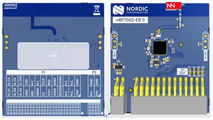
The nRF7002 EB II is a versatile evaluation kit in the form of a thumbstick shield which connects to compatible Nordic host boards using the Nordic expansion header.
The nRF7002 EB II unlocks low-power Wi-Fi 6 capabilities for your host device. It supports dual-band Wi-Fi 2.4GHz and 5GHz, and is based on the nRF7002 SoC. The shield also supports nRF7001 and nRF7000 SoCs through variant overlays. Seamlessly connect to Wi-Fi networks and leverage Wi-Fi-based locationing, enabling advanced features such as SSID sniffing of local Wi-Fi hubs.
Requirements
The nRF7002 EB II board is designed to fit straight into a Nordic expansion header and uses SPI as the communication interface. Any host board that supports the Nordic expansion header can be used with the nRF7002 EB II.
Prerequisites
The nRF70 driver requires firmware binary blobs for Wi-Fi operation. Run the command below to retrieve those files.
west update
west blobs fetch nrf_wifi
Usage
The shield can be used in any application by setting --shield nrf7002eb2 when invoking
west build.
Console and UART impact
On nRF54L15 DK and nRF54LM20 DK, the expansion header pins conflict with the pins used by Virtual Serial Port 1 (VCOM1).
Because the application core (CPUAPP) is essential, the shield overlay disables the conflicting UART20 and reroutes the application console (including shell, mcumgr, and Bluetooth monitor) to UART30, which maps to VCOM0.
Key changes and requirements
Virtual Serial Port Swap: The application console moves from the secondary port to the primary port (the first enumerated VCOM port on your OS). You must use this primary port (e.g. the lower-numbered ttyACM on Linux or COM port on Windows) for all shell, flashing, and mcumgr tasks.
Mandatory Step: VCOM1 (the secondary port) must be disabled in the nRF Connect Board Configurator for the shield to function.
Physical Limitation: Since VCOM1 is electrically blocked by the shield, only one virtual serial port (VCOM0) remains functional.
FLPR Core: Because the application core claims the only functional port (VCOM0), the FLPR core has no UART output by default. Even if FLPR is remapped to a different UART instance via an overlay, it cannot be routed to the PC via USB unless the application core’s console is disabled to free up the VCOM0 gateway. As a fallback for FLPR console output when using the shield, use the
rtt-consolesnippet.
UART and port mapping
Caution
If you have multiple devices connected, identify the primary port for this specific board. Using the secondary port (VCOM1) while the shield is attached will cause pin conflicts and hardware instability.
Shield Variants
The nRF7002 EB II has several variants to support different nRF70 SoCs and features:
nrf7002eb2: The default variant using the nRF7002 SoC.nrf7002eb2_nrf7001: Variant using the nRF7001 SoC.nrf7002eb2_nrf7000: Variant using the nRF7000 SoC.nrf7002eb2_coex: Adds SR co-existence pins only. It cannot be used standalone; it extends one of the main shields (e.g.nrf7002eb2ornrf7002eb2_nrf7000) by passing both in a single--shieldargument, for example:--shield "nrf7002eb2;nrf7002eb2_coex".
SR Co-existence
The nRF7002 EB II supports SR co-existence provided the host board supports it. The SR co-existence
pins are connected to the host board’s GPIO pins. Enable it by using the nrf7002eb2_coex shield
together with one of the main shields (see Shield Variants above).
Two Kconfig options are available to enable SR co-existence:
CONFIG_NRF70_SR_COEX: Enables SR co-existence.CONFIG_NRF70_SR_COEX_RF_SWITCH: Control SR side RF switch.